SMALL: Spherical Microphone Array Little Library
Introduction
In this tutorial, we’ll learn how to easily build an Ambisonic microphone using the Spherical Microphone Arrays Little Library (SMALL).
SMALL1 is an open source project consists of:
- A set of Computer Aided Designs (CAD) for open or rigid Spherical Microphone Arrays (SMA) mechanical structures, ready to 3D-print.
- Signal processing algorithms, available through ambitools, to encode the SMA signals to Spherical Harmonics signals.
- Python tools to use a robotic arm for the SMA acoustic calibration, in a research context.
More infos on this project can be found in the repository or by reading this paper1.
Although SMALL allows a multitude of SMA configurations, we focus in this tutorial on the realization of a 45 mm radius, 2nd order SMA (i.e., Ambisonic microphone), using 14 MEMS PDM microphones, with an embedded USB sound card. The microphone location o the sphere are according to a Lebedev2 grid with 14 nodes.
List of Material
To build and use the microphone you will need:
Software:
- openSCAD,
- PrusaSlicer >= 2.6 or equivalent 3D printer slicer,
- SMALL: retrieve the repository here,
- ambitools >= v1.3.
Hardware:
- A 3D printer with filament,
- A MiniDSP MCHStreamer,
- 14x Adafruit PDM microphone breakout boards,
- 1x PDM Hat for the MCHStreamer. The gerber files are available in SMALL repository, see here
- Small AWG wires,
- Silicone of PU glue,
- Duct tape,
- 4x 10 mm M3 screws with nuts,
- 1x M5 threaded rod for the mic stand.
Procedure
Compile the STL files
The SMA shell is made of two parts that are designed in openSCAD. One will use this software and the SMALL repository to compile the two correponding STLs.
If you don’t want to compile the STL files, you can skip this part and directly retrieve the STLs here
- In SMALL repository open the openSCAD file
/cad/sma_rigid.scad. In the customization panel, selectlebedev14preset. The preview for thetop_shell_all()module (left panel) should look like this:
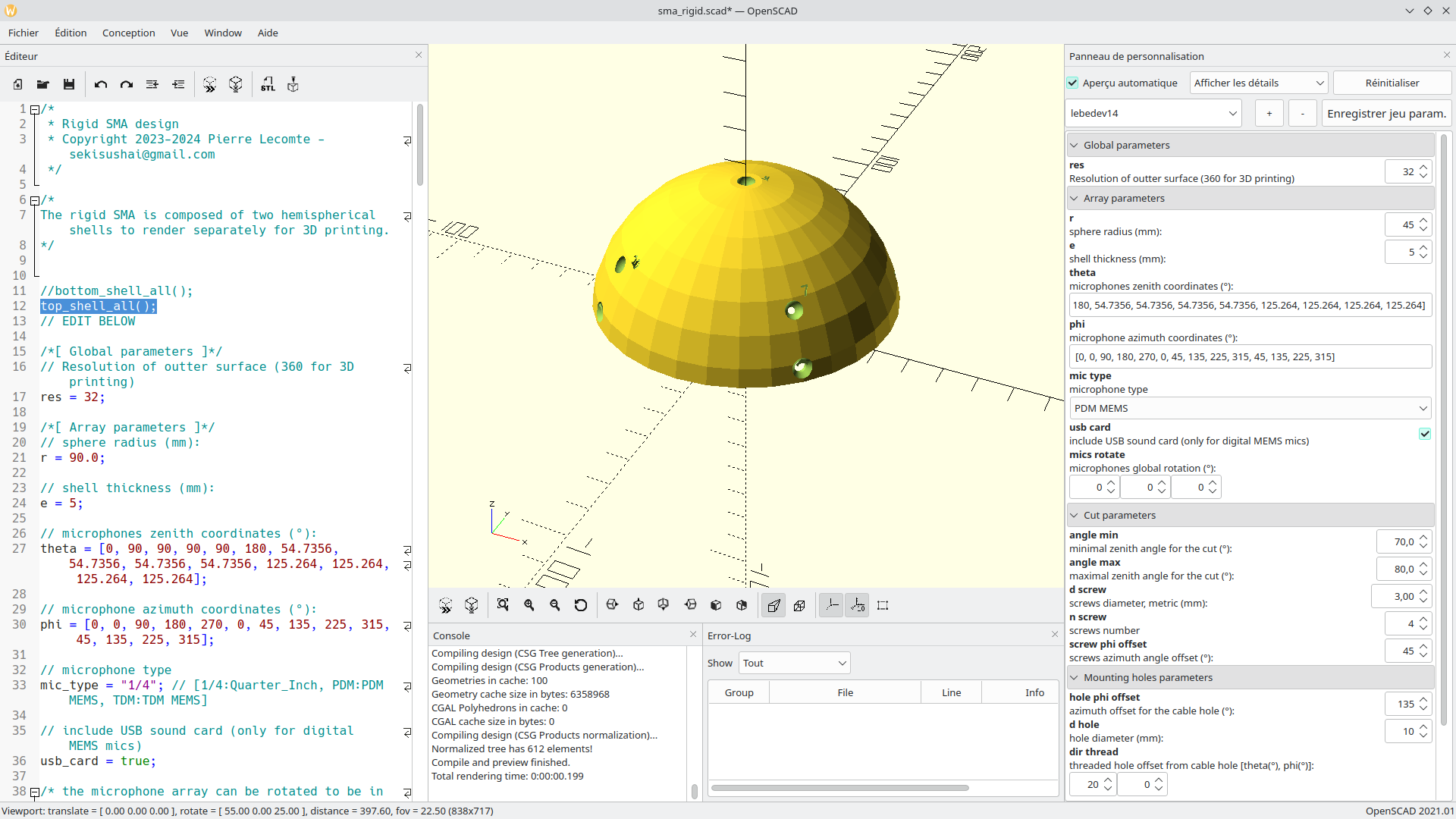
lebedev14 preset and the top_shell_all() module.You can see in the right panel a mutlitude of parameters that can be changed, but the preset should work without modifying anything except the first parameter, res.
- Change this parameter to
res=360and hit F6 (render). This should take up to several minute to render. Once this is done you should see something like this:
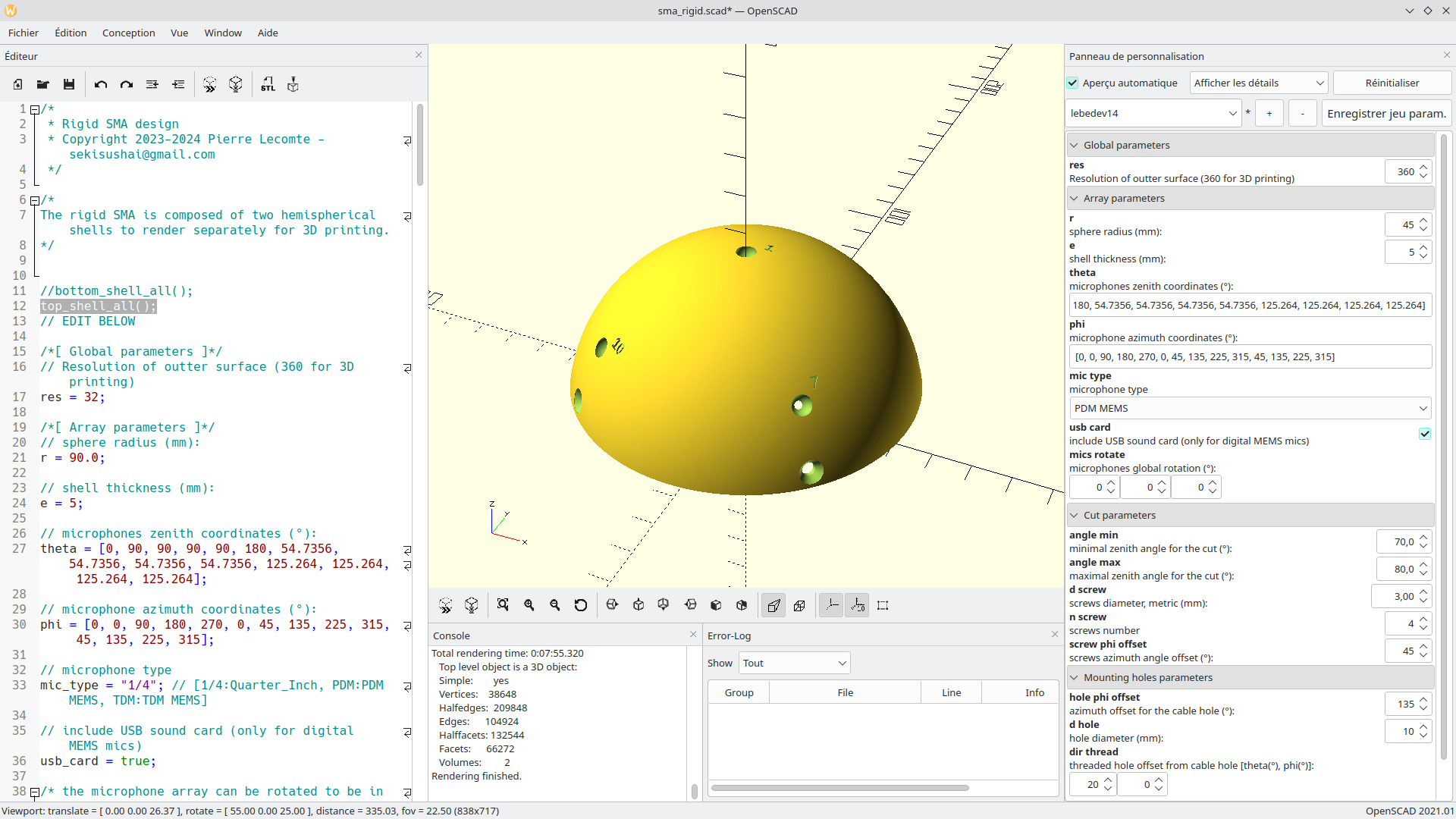
lebedev14 preset and the top_shell_all() module.- Save the resulting STL (F7) to a file named (for instance,
lebedev14_top.stl). - In the left panel, comment out the line
top_shell_all()and uncomment the linebottom_shell_all(). Then hit render (F6) again. After several minutes, you should see something like this.
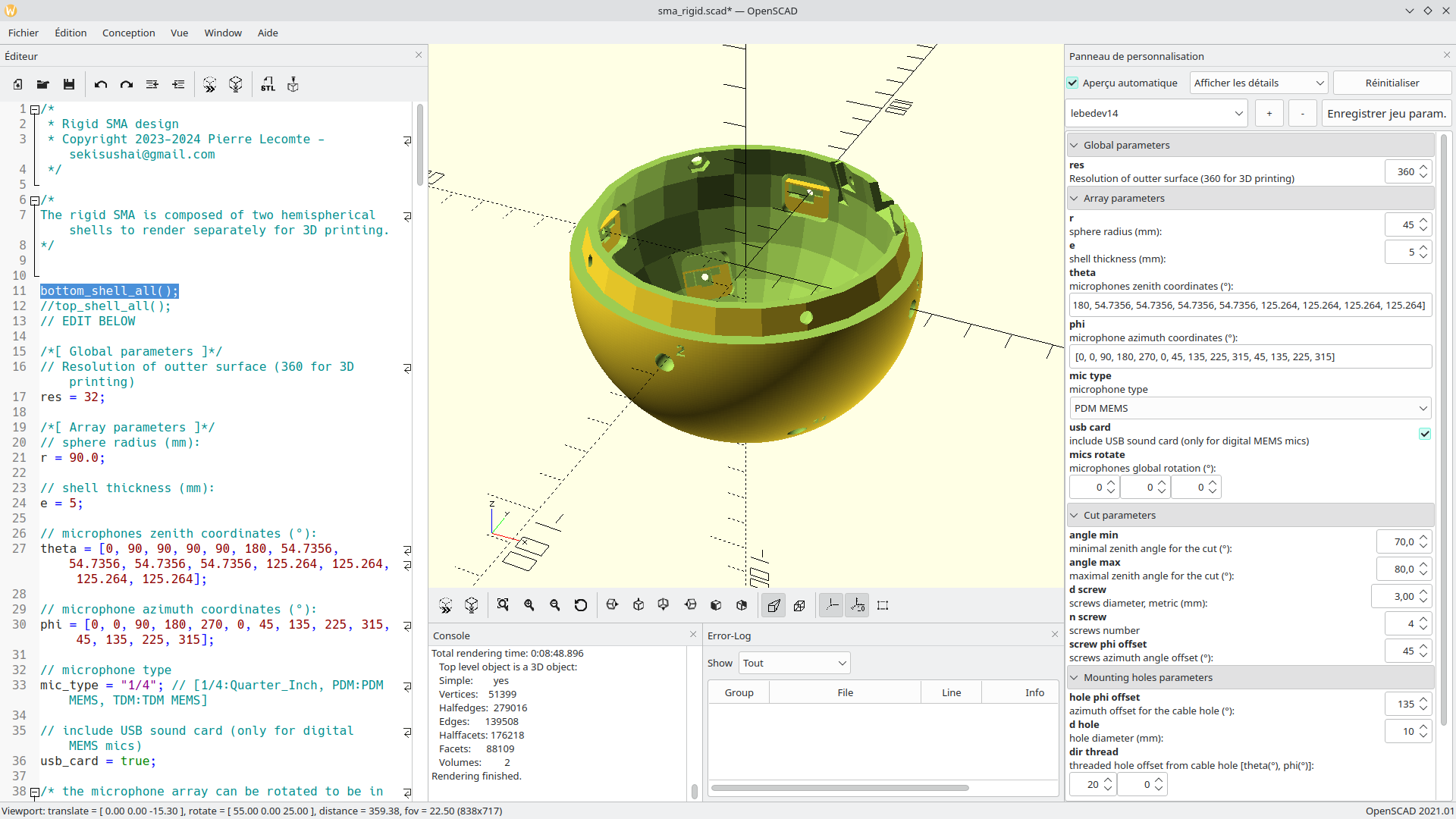
lebedev14 preset and the bottom_shell_all() module.- Save the resulting STL (F7) to a file (for instance
lebedev14_bottom.stl).
3D print the spherical shells
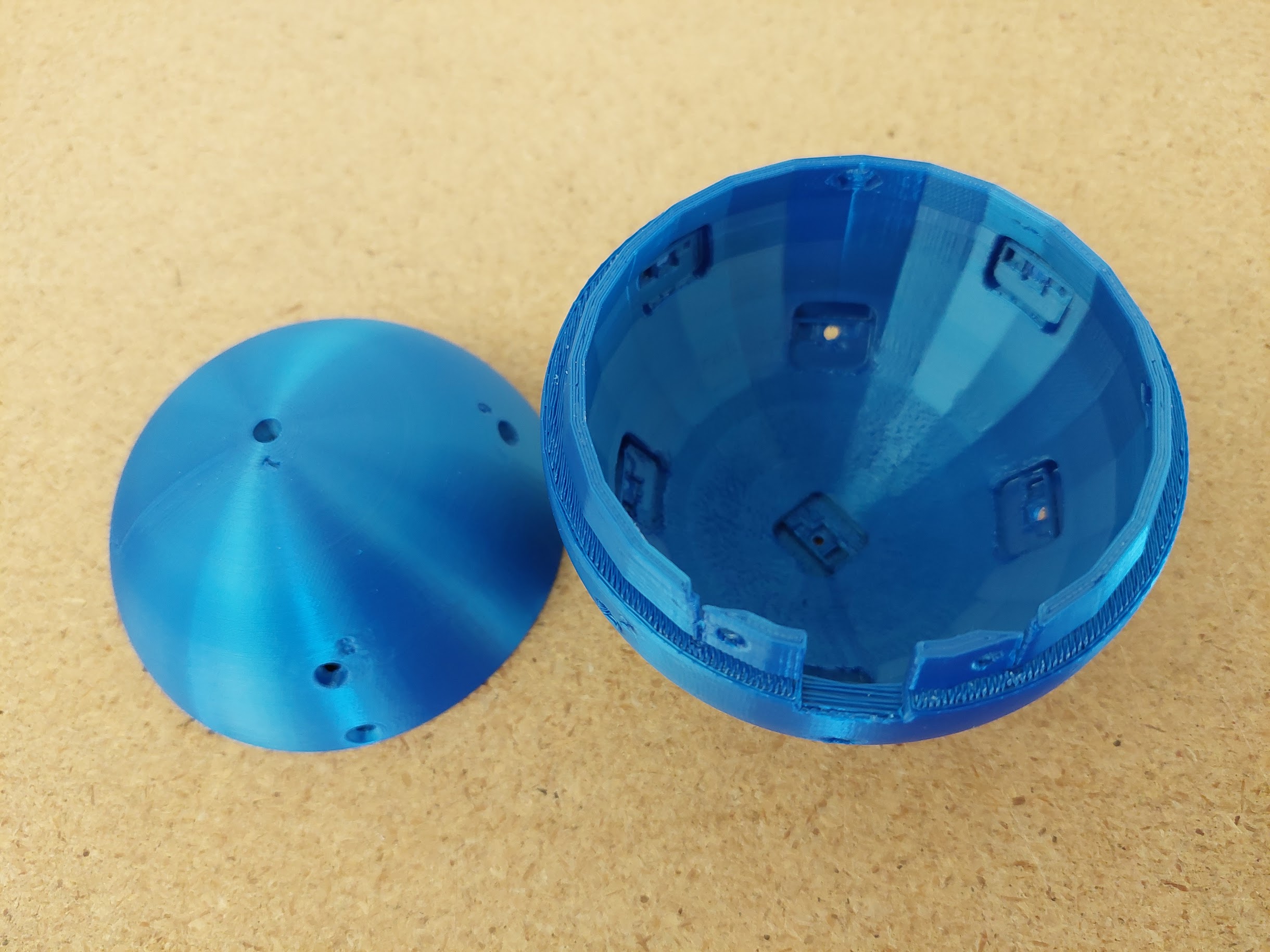
The next step is to print the top and bottom part of the Spherical Microphone Array (SMA). In this tutorial, one uses the PrusaSlicer software to configure the print, but any (good) slicer might do the job. One starts with the file lebedev14_top.stl:
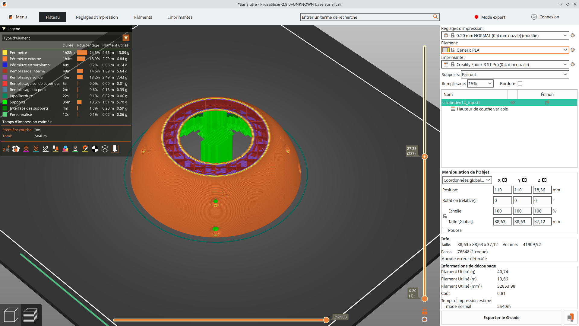
- A layer height of 0.2 mm everywhere will give a bad surface quality at the top and bottom of the shell. To increase the surface quality and decrease the problematic overhang zones without increasing too much the printing time, one uses the variable layer height option. The layer height should be reduced in the problematic zone such as in the following figure:
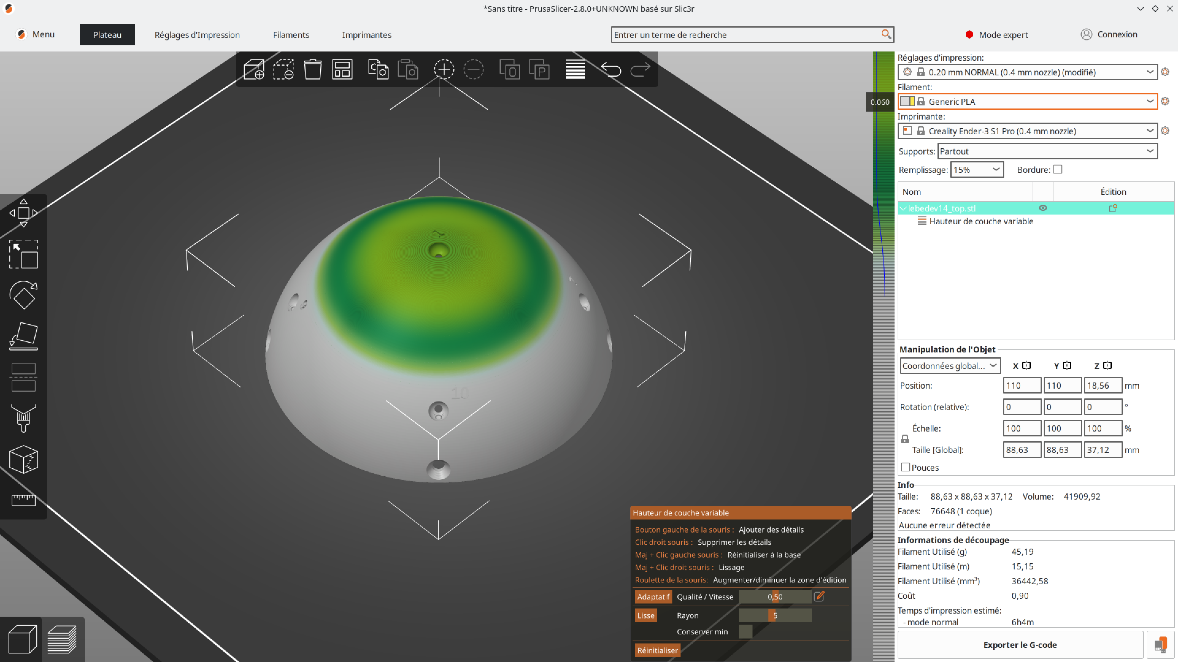
- Support needs to be activated. An overhang angle of 10° is sufficient (in conjunction with variable layer height option):
- Same settings should be fine for the
lebedev14_bottom.stlfile. Don’t forget to rotate the part 180° around x- or y- axis.:
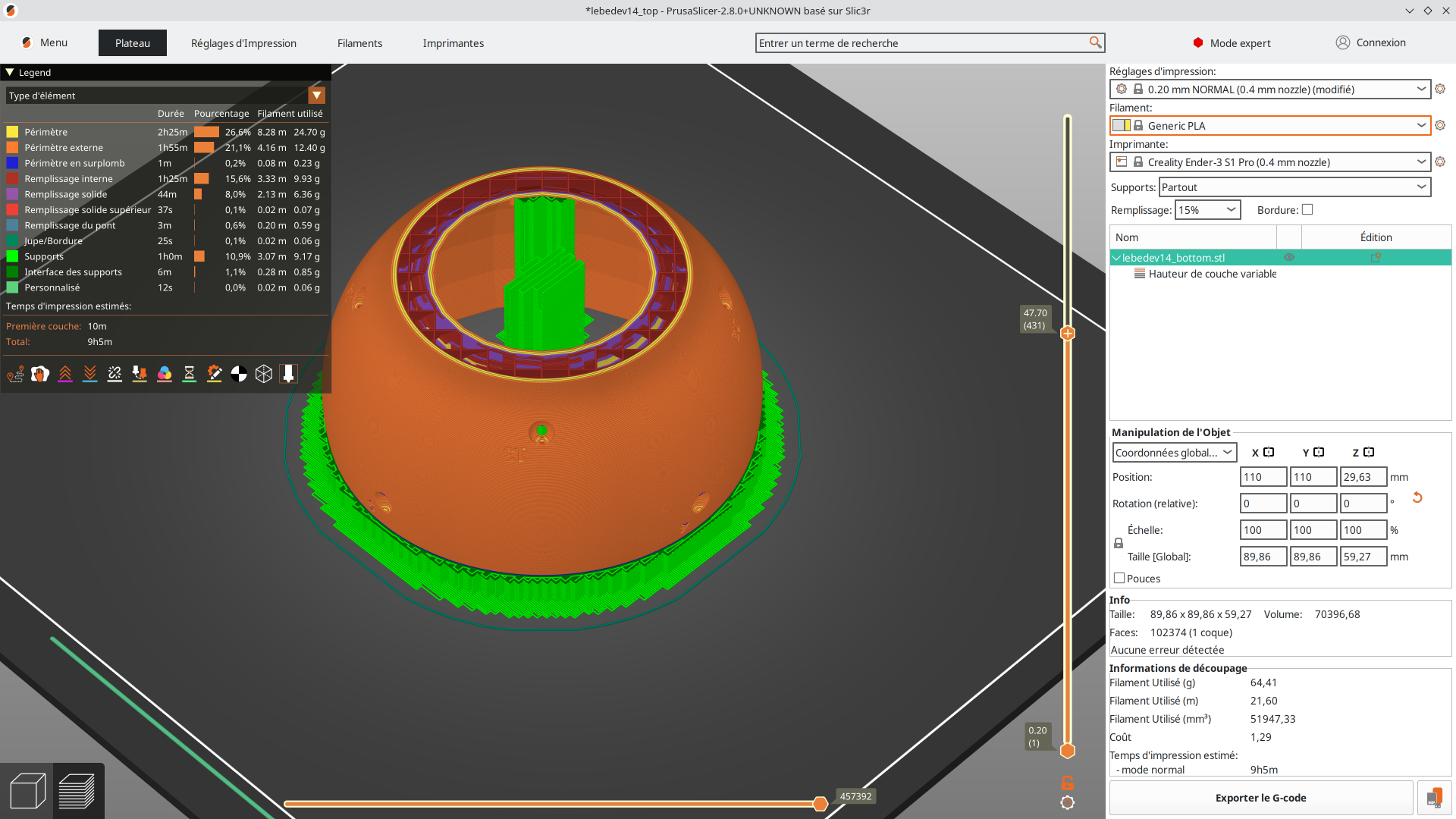
lebedev14_bottom.stlThe PrusaSlicer .3mf project files are available here.
Assembling the microphone array
To assemble the SMA, the first step is to solder the 14 PDM microphones to the MCHStreamer hat. The PDM microphones are soldered by two in daisy chain to form a stereo pair with L(eft) and R(ight) channel. The MCHStreamer hat can take up to 8 stereo pairs (16 channels), but only the first 14 channels are used here.
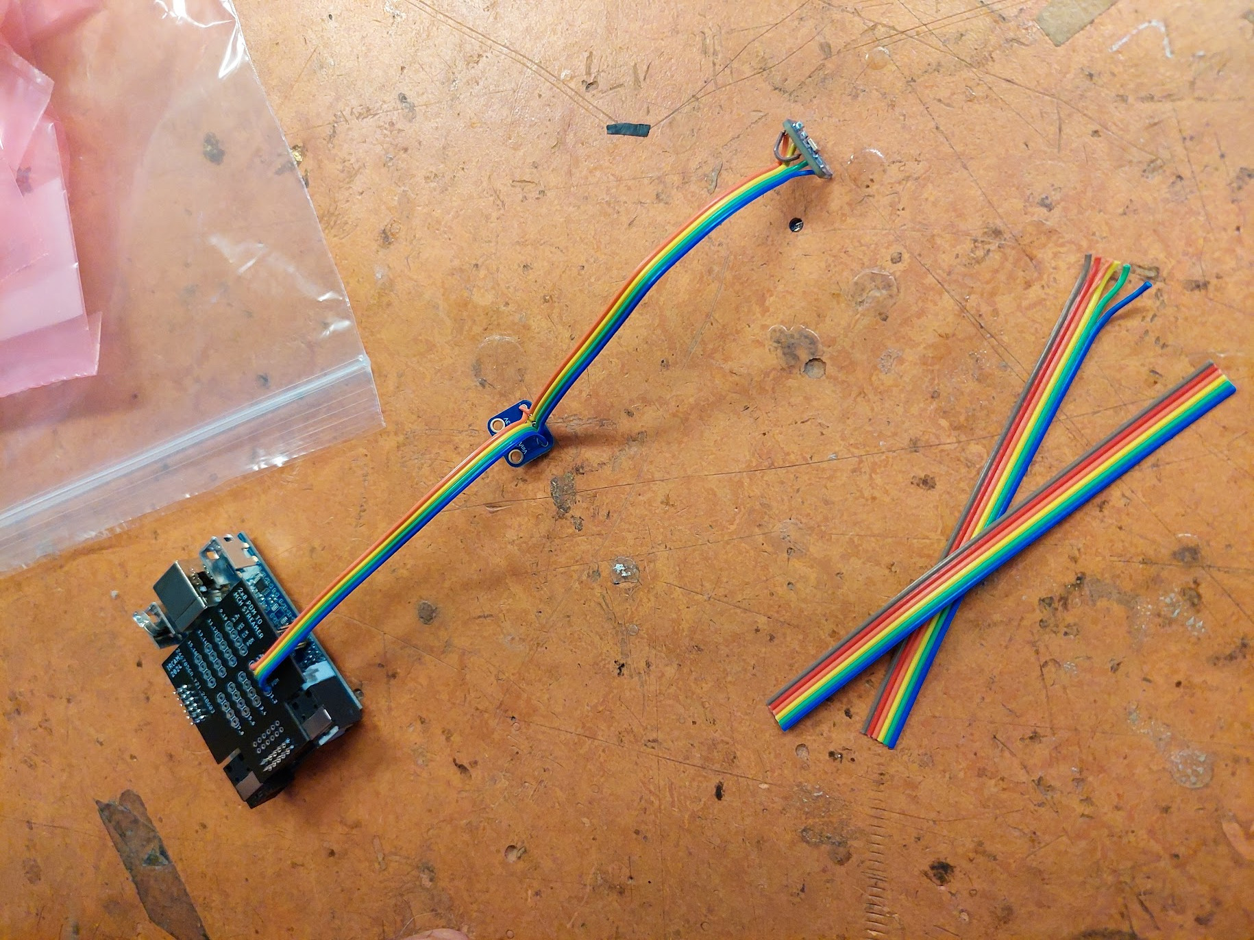
The first of the two microphones is assigned to the L channel. The SEL pin must therefore be soldered to the GND pin (see the pinouts here). Use a small piece of wire to do so.
In addition, the wires to this microphone must be duplicated to feed the R channel microphone. Use small AWG wires ~10 cm long:
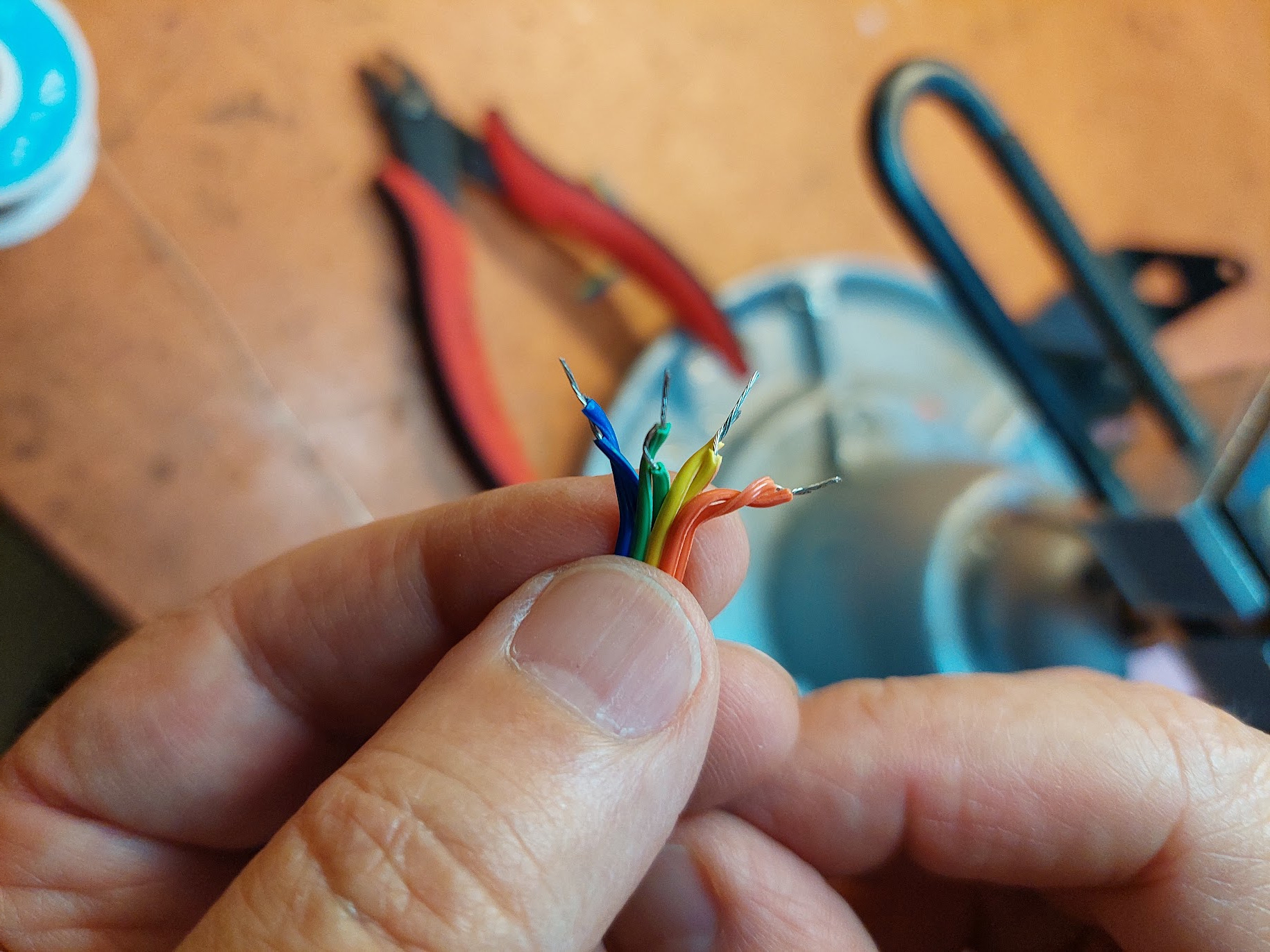
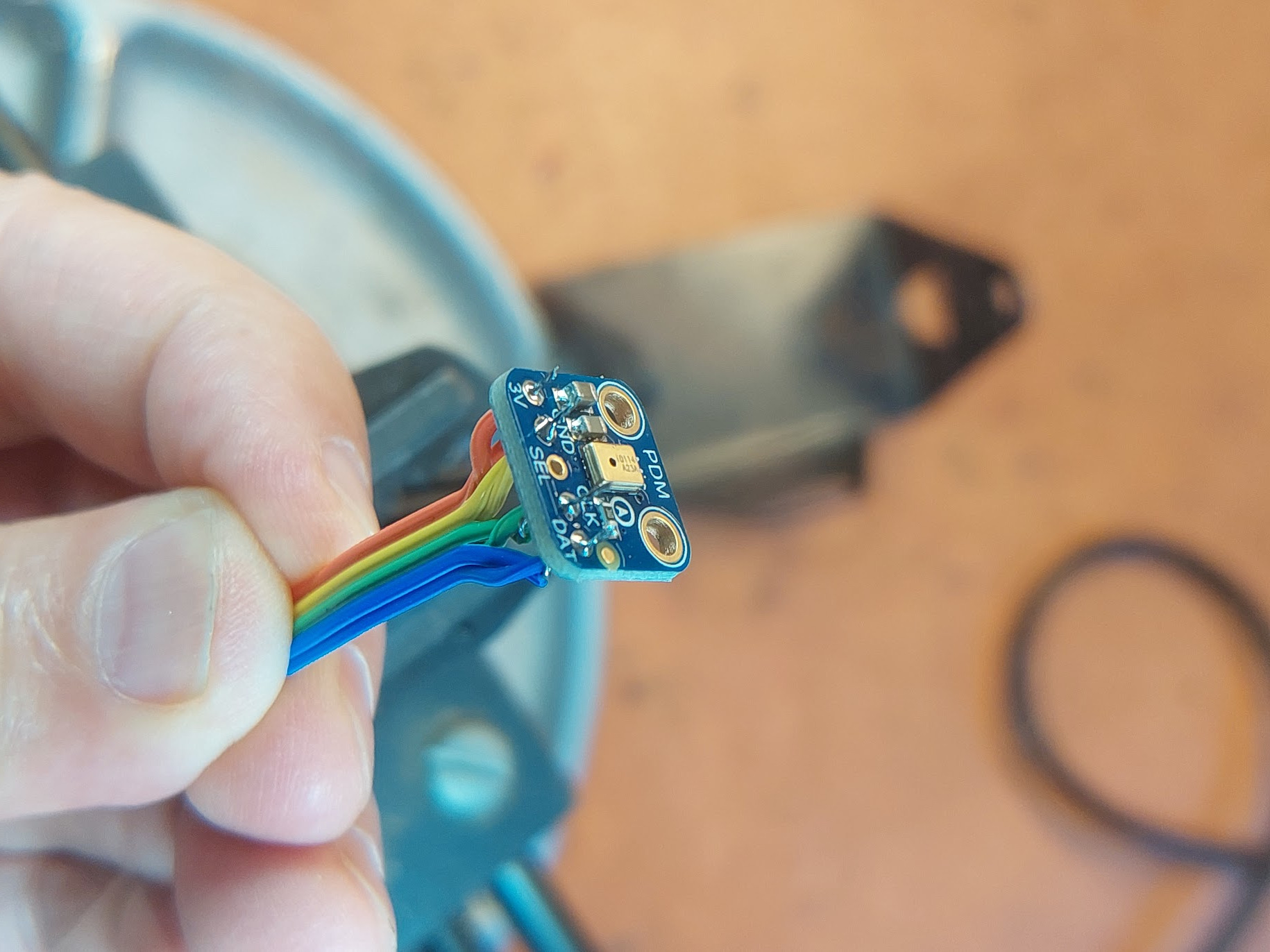
Solder the wires from the back of the board, i.e. the other side of the microphone capsule:
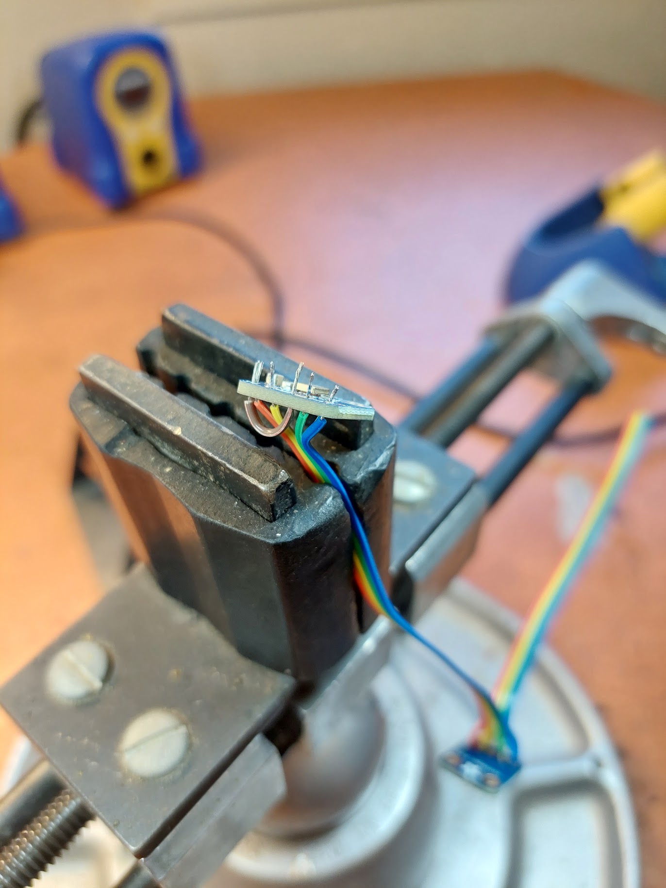
The L channel microphone SEL pin must be soldered to the 3V pin (see the pinouts here). Use a small piece of wire to do so:
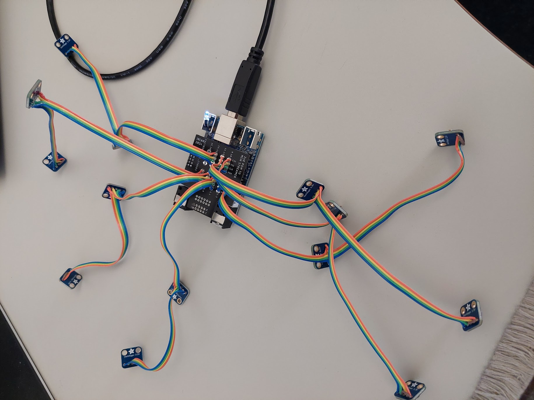
Once the microphones are soldered in pairs, they can be easily inserted into the corresponding slots.
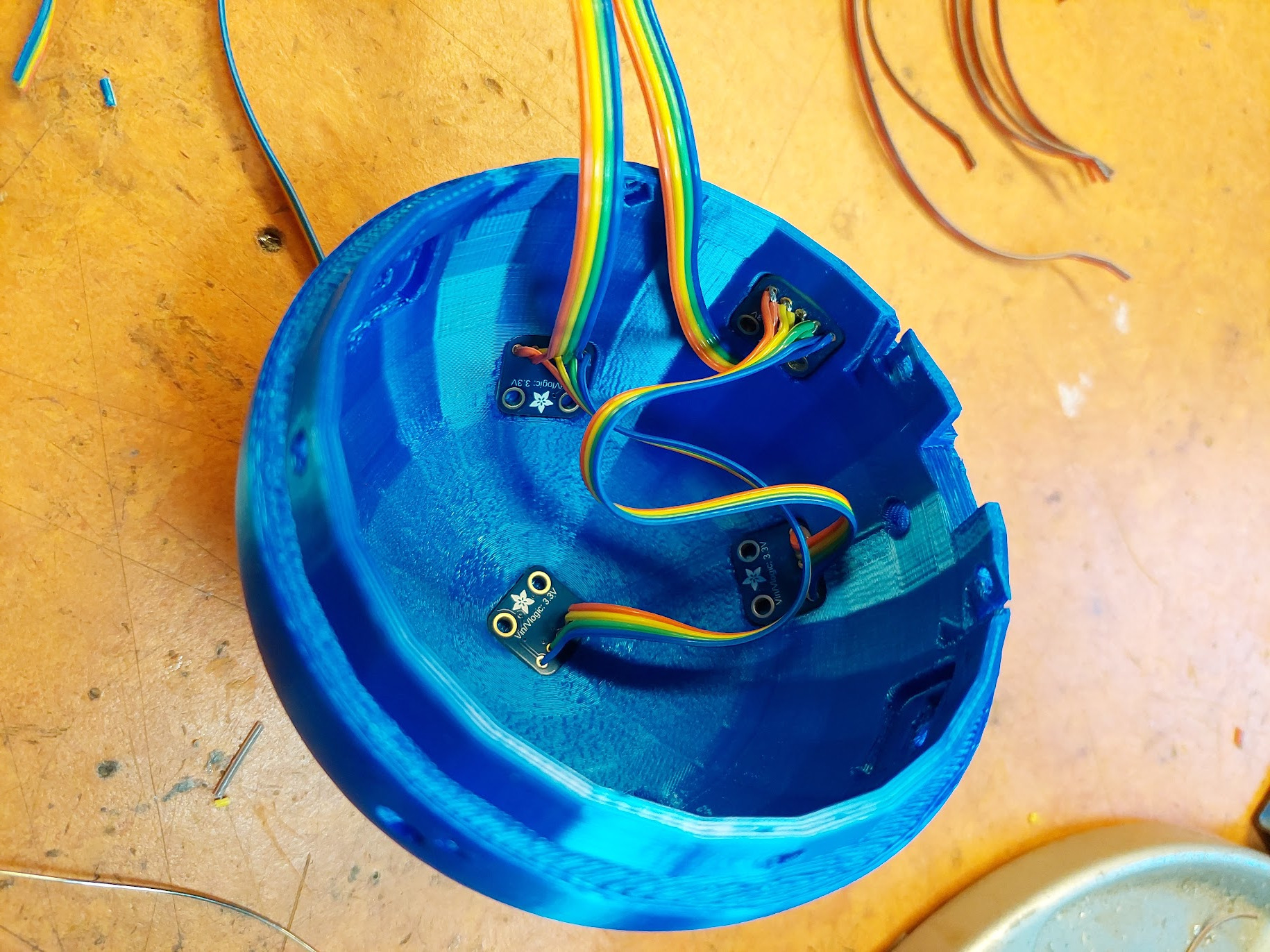
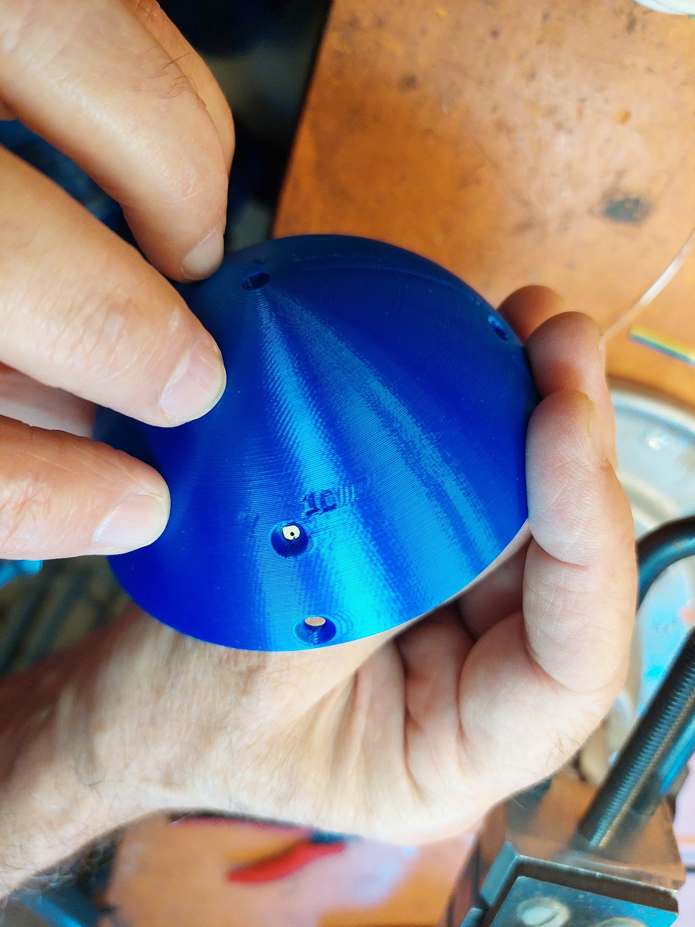
Important : the channel number printed on the MCHStreamer hat should correspond to the number printed on the outside of the shell.
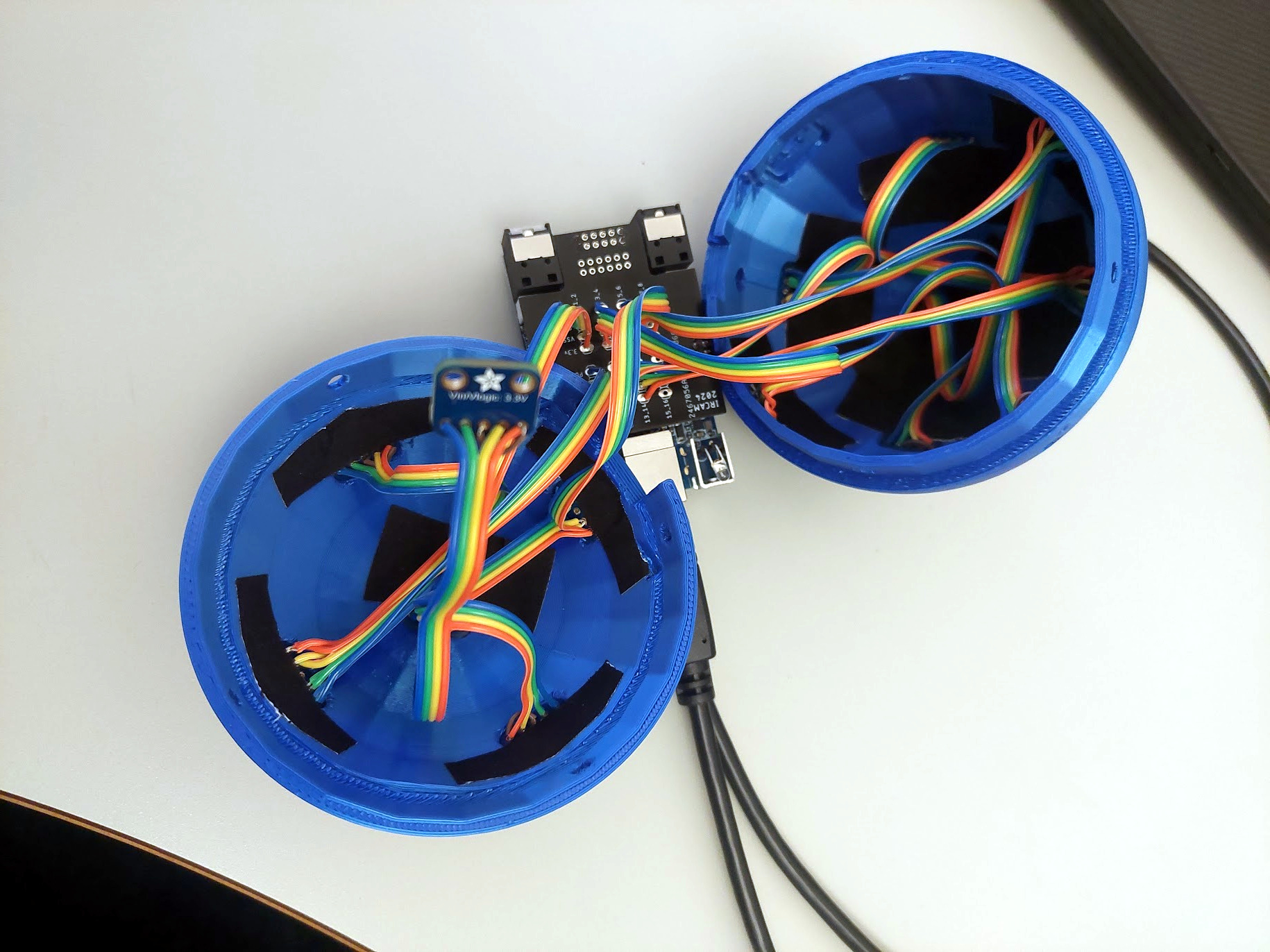
To prevent the microphones from popping out of place during assembly, use gaffer or duct tape to hold them in place. However, it is best to “glue” them in place to ensure that the inside of the sphere is sealed from the outside by the microphone holes, thus optimizing acoustic performance.
Finalize the mounting by inserting the MCHStreamer in the correponding slot
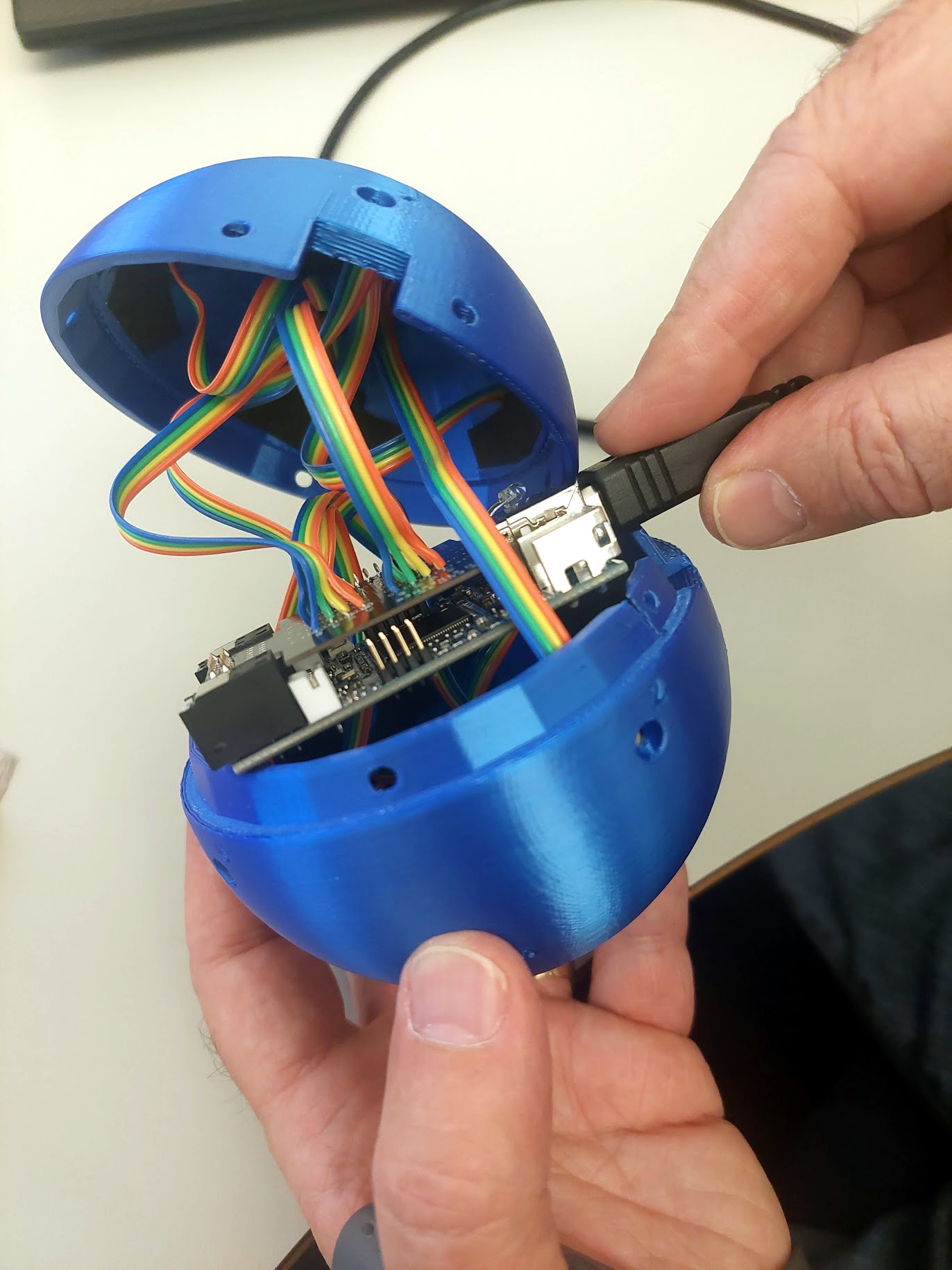
Use 4x M3 screws and nuts to join the two half spherical shells together.
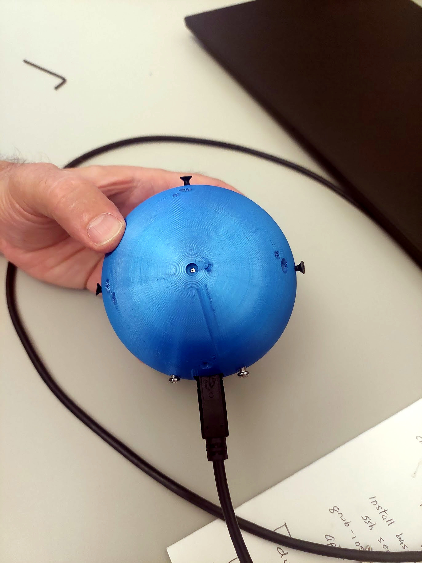
Finally, use the M5 threaded rod for the SMA stand:
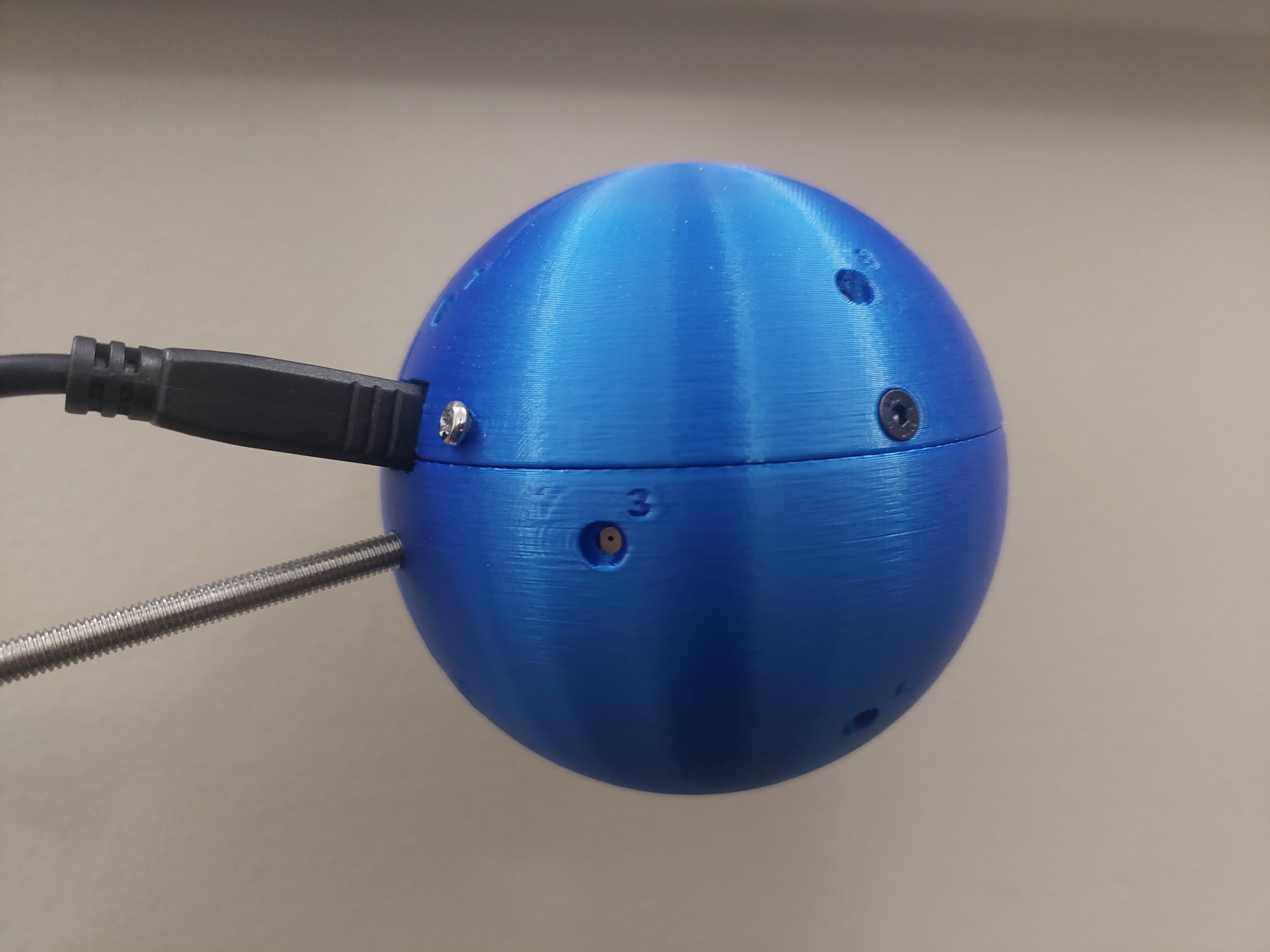
Example of use
More infos
-
P. Lecomte, “SMALL: Spherical Microphone Arrays Little Library”, Forum Acusticum 2023, 10th Convention of the European Acoustics Association, Turin, Italy, 2023. ↩ ↩2
-
V. Lebedev, “Values of the nodes and weights of quadrature formulas of Gauss-Markov type for a sphere from the ninth to seventeenth order of accuracy that are invariant with respect to an octahedron,” USSR Computational Mathematics and Mathematical Physics, vol. 15, no. 1, pp. 44–51, 1975. ↩